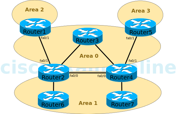
You administer the OSPF network shown in the diagram. Area 1 is configured as a standard area. Area 2 and Area 3 are configured as stub areas. Router3 fails. Several routes are lost throughout the network.
Which of the following actions can you take to restore the lost routes?
| A. |
Configure Area 1 as a stub area. | |
| B. |
Configure Area 2 and Area 3 as standard areas. | |
| C. |
Create a virtual link between Router1 and Router5. | |
| D. |
Create a virtual link between Router2 and Router4. | |
| E. |
Configure the Fa0/0 interfaces on Router2 and Router4 to be part of Area 0. | |
| F. |
Configure the Fa0/1 interfaces on Router2 and Router4 with IP addresses that were configured onRouter3. |
You can take either of the following actions to restore the lost routes:
- Create a virtual link between Router2 and Router4.
- Configure the Fa0/0 interfaces on Router2 and Router4 to be part of Area 0.
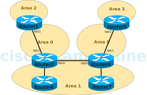
In this scenario, the backbone area, Area 0, has become discontinuous, or partitioned, as shown in the following network diagram:

To connect a backbone area that has become discontinuous because of the loss of a router or the loss of a link between two routers, you can create a virtual link.
The routers at each end of the virtual link must adhere to the following restrictions:
- Both routers must connect to the backbone area.
- Both routers must share another common area, which is used as a transit area.
- The transit area cannot be a stub area.
- The transit area cannot be the backbone area.
To create a virtual link, you should issue the area area-id virtual-link router-id command in router configuration mode on the routers at each end of the virtual link, where area-id is the transit area ID and routerid is the router ID of the router at the other end of the virtual link. For example, if the router ID of Router4 were 1.2.3.4, you would issue the area 1 virtual-link 1.2.3.4 command on Router2. You would also issue a similar command on Router4 by using the router ID of Router2 as the router-id parameter.
Alternatively, you can configure the Fa0/0 interfaces on Router2 and Router4 to be part of Area 0. Doing so would make Area 1 discontinuous. This is acceptable because interarea traffic must pass through the backbone or a transit area; therefore, nonbackbone areas can be discontinuous. The discontinuous Area 1 partitions would be advertised to one another through inter-area routes instead of intra-area routes.
Configuring Area 1 as a stub area will not restore the lost routes. Additionally, configuring Area 1 as a stub area eliminates the possibility of using a virtual link to connect the discontinuous backbone areas.
Configuring Area 2 and Area 3 as standard areas will not restore the lost routes. Changing a stub area to a standard area will only allow Type 5 external summary routes to be advertised throughout the area.
You cannot create a virtual link between Router1 and Router5. For a virtual link to be created, both routers must share a common area. If Router1 and Router5 shared a nonstub area, you could create a virtual link between them and the lost routes would be restored.
Configuring the Fa0/1 interfaces on Router2 and Router4 with IP addresses that were configured on Router3 will not restore the lost routes. The routes were not lost because of the unavailability of the IP addresses on Router3; the routes were lost because of the discontinuous backbone area.